Perspective Correction
Below is the 3.4mm version where the maximum FOV of the fisheye lens is utilized.
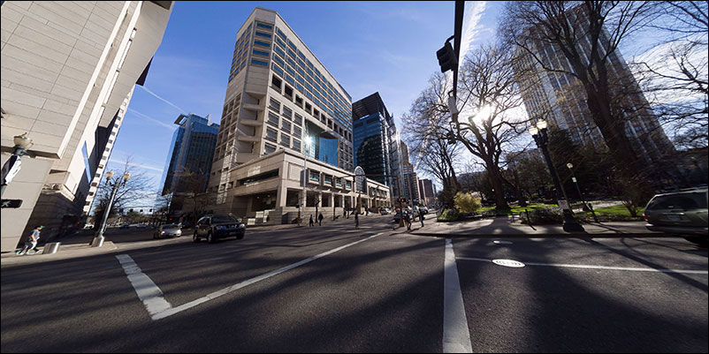
Notice how vertical lines converge toward the top of the frame. This is perspective distortion and can be corrected in PTGui by dragging the image in the Editor until the lines are parallel. A more accurate method, and the one used here, is to specify Vertical Control Points. Click on the following image for a larger view.
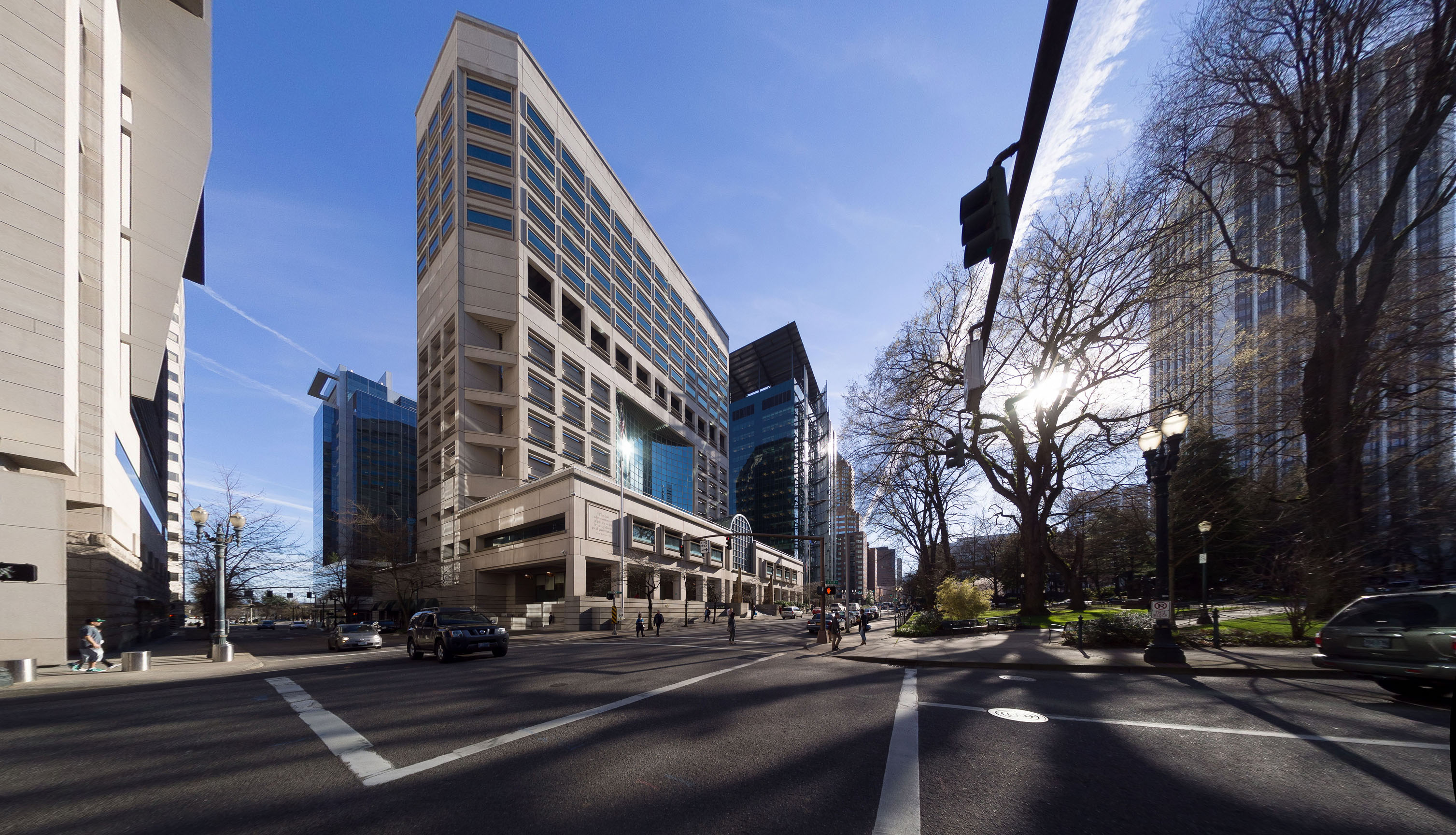
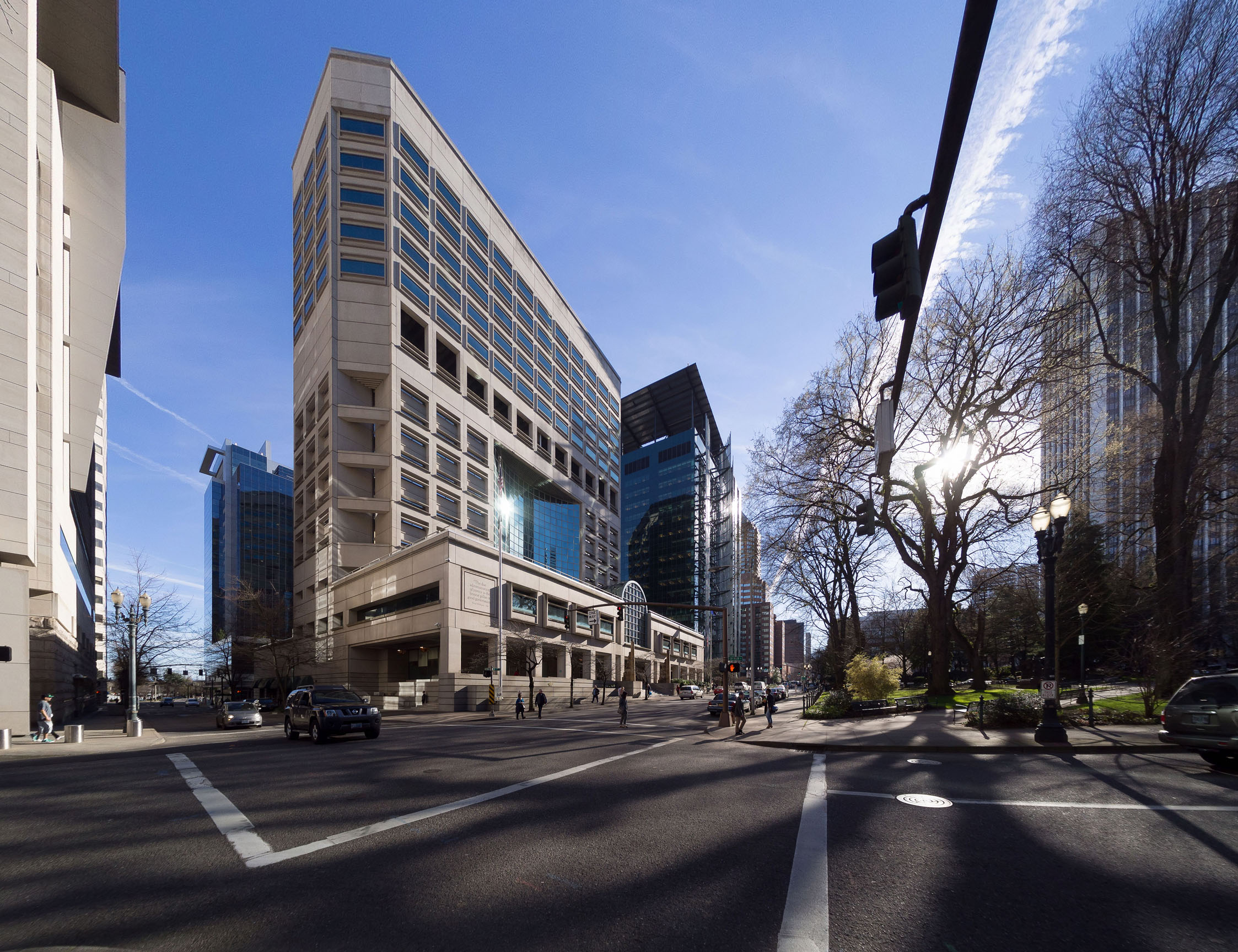
The stretched portions at the left and right edges are easily compressed with a Panini (Vedutismo) projection. Click on the following image for a larger view.
To correct perspective with Vertical Control Points proceed as follows. In PTGui choose the Control Points tab, select Vertical Line (lower left corner), and draw two lines. Recall that a line is determined by two points. Scroll the image and find a vertical straight-line feature near one of the sides. Click once in the left pane near the top of the feature, then click again in the right pane near the bottom of the feature. These two points define a line. Scroll to the opposite side of the image and add two more points to another vertical straight-line feature. Then click on the Optimizer tab and Optimize. Now both lines will run straight up and down and they will be parallel.
To understand how the optimizer works, imagine you are at the center of a globe. The globe is marked with longitude lines (meridians) that run from the North Pole to the South Pole. The image is, in effect, mapped to a sphere and projected to a flat surface (rectilinear projection).
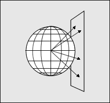
Features near the equator project directly onto a flat surface. Features that are near the poles travel a further distance to the surface and, as a consequence, are magnified. In this way the longitudinal lines, that converge on the globe, appear parallel when projected. The distortion present in fisheye lenses is similar in nature and this is how it is corrected.
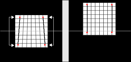
While this works fine for shots taken where the sensor is parallel to the target, when the camera is tilted the image must be shifted on the sphere to compensate for the tilt. The following figure illustrates perspective distortion for a tall building when the camera was tilted. Vertical Control Points have been specified and two lines have been drawn. By mapping the image closer to the North Pole, as shown in the figure on the right, magnification for the top portion of the image increases and the lines are now parallel.
A similar procedure can be done to align horizontal features with Horizontal Control Points. After optimization you'll find the image has shifted. Simply move the sliders in the Editor to give an increased field of view and export the image. You can always crop off the excess during post processing.